Photovoltaic inverter wiring cable main line

Everything You Need to Know About Solar Wires and Cables
The AC connection cable interconnects the solar power inverter to the protection equipment and the electricity grid. For small scale solar systems with three-phase inverters, a

The Complete Guide to Solar Panel Wiring Diagrams
Solar panel diagrams are graphic representations of the connections you should make between each PV module and other components of the solar power system, including: Solar inverter; Charge controller; Solar

Wiring solar panels
Solar photovoltaic (PV) panels can be wired to increase voltage and/or current. Caution: Dangerous voltages can be produced when panels are connected together. Some smaller panels are fitted with an output junction

How To Connect Inverter Main Line
Can I Get A Connection Diagram Of Solar Panel And Inverter Quora. Arduino Inverter Circuit. Technical Requirements For The Connection Of Inverter Energy Systems Ies

The Complete Guide To Solar Panel Wiring Diagrams
Electrical wiring and components, including cables, connectors, junction boxes, and breakers, form the backbone of your solar energy system. Use high-quality, weatherproof wiring and components that meet or exceed local electrical

Photovoltaic Cable Basics: From Selection To
What is pv cable? Photovoltaic wire is a wire designed for solar power systems. They are like adhesives that act as a nodal point among different solar components. They link the panels to the other vital parts.Here I
Solar Cable Size Selection Guide For PV Plants
1. Solar Panel PV Wire. It is a well-known solar power wire that is used for connecting cabling in photovoltaic installations. The XLPE cable insulation provides

Electricity losses online calculator : AC and DC electrical wire
a : number of line coefficient, a=1 for single line, a = 3 for 3-phase circuit. R : resistance of one active line Ib : current in Ampere (A) R is given by the next formula : R = b x ρ1 x L / S b :

How to Wire Solar Panels to Inverter: Complete Guide
Here are the connection steps to follow: Step 1: Locate the positive and negative terminals of your panel connection and the corresponding DC input terminals of your inverter. Step 2: Connect the positive terminal of

Novel Crossover Wiring of DC Cable for Photovoltaic Array
3.7 Crossover Wiring for Multiple Photovoltaic Arrays. In a large-scale PV plant, several modules are installed above the mounting system, forming a unit, and a number of PV

Installation Overview & Single-Line Diagrams
Installation Overview & Single-Line Diagrams. Created by Victor Herrera, Modified on Fri, Jun 10, 2022 at 11:22 AM by Victor Herrera Wiring the Inverter . 5.

SolarEdge Recommended AC Wiring – Application Note
In some PV installations, the wiring between the inverter AC output and the utility grid connection point covers large distances. In these cases, wire size should be increased to limit the voltage

Photovoltaics in Buildings
2.1.5 String cables 13 2.1.6 Main d.c. cable 15 PV systems include d.c. wiring, with which few electrical installers are familiar. Main Consumer Unit d.c. disconnect Inverter DISPLAY

How to Wire Solar Panels to Inverter: Complete Guide
Once you have wired your solar panels in the desired configuration, you need to connect them to the inverter using the appropriate connectors and cables. Here are the

StorEdge Single Phase Inverter Wiring and On Site Check
MAN-01-00642-1.2 StorEdge Single Phase Inverter Wiring and On Site Check Quick Guide Connecting System Components Connect the system components as shown in the diagram

DIY PV System Installation -
I did this wiring before connecting the micro-inverter cables to the PV panels, and before connecting the new circuit breaker to the house power, so there was no power

Solar Panel Wiring Diagram for All Setups [+ PDFs] – Solartap
How Does Solar Connect to the Main Panel? Solar panels connect to the main panel or breaker box through wire that first passes through the charge controller and the

SURGE PROTECTION FOR PHOTOVOLTAIC SYSTEMS
solar PV system wire loops. These transient currents the solar PV panel and the inverter are likely to be damaged. Only the inverter will be damaged if the (on the main board) LENGTH

Technical specifications for solar PV installations
650kW. The red line represents the peak output of a Solar PV system with peak power 650kWp. Demand peaks and solar PV generation peaks align well in the case of typical office buildings.

Design and Sizing of Solar Photovoltaic Systems
7.6 Cables & Wiring CHAPTER - 8: DESIGN AND SIZING OF PV SYSTEM 8.4 System Sizing 8.5 Battery Sizing 8.6 PV Array Sizing 8.7 Selecting an Inverter 8.8 Sizing the Controller 8.9

4. Wiring
The output of the inverter terminals are wired to the VE Panel AC output terminal busbars. Correctly sized conductors are prewired from the VE Panel breakers to connect to the inverter AC line and neutral input and output. AC1 in line and

Step-by-Step Guide: Wiring Diagram for Hybrid Solar Inverter
Overall, a hybrid solar inverter wiring diagram provides a clear understanding of how solar power systems are interconnected. By visualizing the various electrical connections, homeowners
Solar panel wiring basics: How to wire solar panels
Most modern solar panel installations use single-conductor Photovoltaic (PV) wire, between 10 and 12 gauge AWG. Wiring is required to connect the solar panels to the charge controller, inverter, and battery (in an off-grid system).

Hybrid inverter main panel wiring for grid
add the transfer switch on the inside as well and feed it a 200 amp grid line to one of input contacts, upper or lower which works best for the switch on the other line contact set, land your inverter output option 2 - 100
Multiple String Inverters
D.C. Cable Cables must be rated, as a minimum, to the voltage and current ratings derived from the PV array. Standard de-rating factors must also be applied (BS 7671). Cables should be

Step-by-Step Guide: How to Connect Solar Panels and
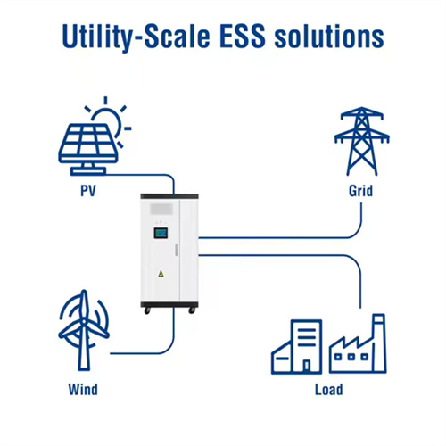
The inverter, in turn, is connected to the utility grid or electrical loads through another set of wires and cables. Solar Panel and Inverter Connection Diagram. The solar panel and inverter connection diagram illustrates the process of
Solar PV Wire, Inverter Cable, Gator Clamps & Fuse Kits
Solar PV Wire; Solar Racks; BATTERIES. Lithium; AGM Lead Deep Cycle; CABLES & FUSE KITS. Inline Fuse Kits; Solar PV Wire UL; 4/0 AWG Cables UL; 1/0 AWG Cables UL; 4 AWG
How to Connect Solar Panels to the Grid: Step-by-Step Guide
Yes, several financial incentives are available for connecting solar panels to the grid in the UK. These include feed-in tariffs (FITs), which provide payments for every unit of

A Step-by-Step Guide: How to Create a Wiring Diagram for Solar
In order to connect multiple solar panels together, you have two main wiring options: series and parallel. Series wiring involves connecting the positive terminal of one panel to the negative
A Guide to Solar Wires, Cables and Connectors
String cables can be connected to an inverter directly or by way of an AC connection, a DC combiner box or the node string technique. Some solar panels have DC cables built in. Main DC Cable: these cables join the junction box

6 FAQs about [Photovoltaic inverter wiring cable main line]
How to connect solar panels to inverter?
Once you have wired your solar panels in the desired configuration, you need to connect them to the inverter using the appropriate connectors and cables. Here are the connection steps to follow: Step 1: Locate the positive and negative terminals of your panel connection and the corresponding DC input terminals of your inverter.
How to wire solar panels together?
Wiring solar panels together can be done with pre-installed wires at the modules, but extending the wiring to the inverter or service panel requires selecting the right wire. For rooftop PV installations, you can use the PV wire, known in Europe as TUV PV Wire or EN 50618 solar cable standard.
How do you wire solar panels in series?
Wiring solar panels in series involves connecting each panel to the next in a line (as illustrated in the diagram above). Just like a typical battery that you may be familiar with, solar panels have positive and negative terminals.
What are the different types of solar panels wires & connectors?
When wiring solar panels, there are very specific types of cables and connectors that you’ll need to get the job done successfully. These include: PV Wire or Solar Cable: These are used to interconnect the solar panels which we have also referred to as stringing.
What type of inverter is used for solar panels?
The type of inverter used for solar panels depends on how it is connected to them. You can use string inverters, microinverters, and power optimizers. Once you have wired your solar panels in the desired configuration, you need to connect them to the inverter using the appropriate connectors and cables. Here are the connection steps to follow:
How to wire solar panels in parallel or series?
Connect the negative terminal of the first panel and the positive terminal of the second panel and connect to the corresponding terminals in solar regulator’s input. The solar regulator will detect the panels and start to charge the battery during sunlight. Wiring solar panels in parallel or series doesn’t have to be an either/or proposition.
Related Contents
- Wiring method for photovoltaic inverter
- Photovoltaic inverter wiring is beautiful
- The AC VW line voltage of the photovoltaic inverter is too low
- Photovoltaic grid-connected inverter wiring method
- Wiring of photovoltaic grid-connected inverter
- Photovoltaic inverter wiring construction
- Photovoltaic inverter connection line plug
- 70kw photovoltaic inverter main parts
- Photovoltaic inverter AC side wiring
- Photovoltaic panel inverter battery connection line
- Photovoltaic inverter DC line process
- 5-core cable for photovoltaic inverter