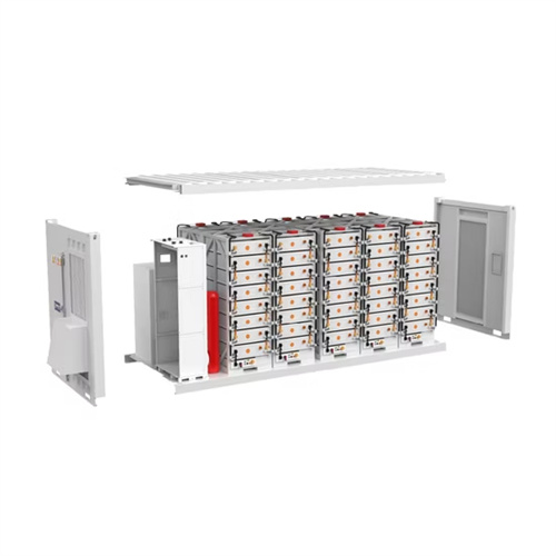
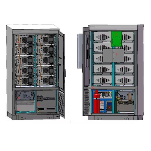
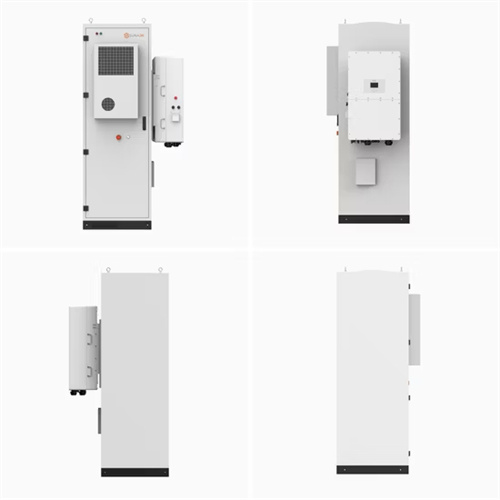
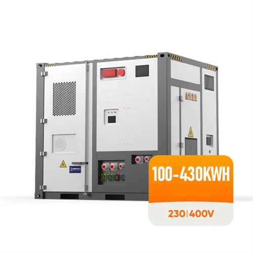
PCS schematic diagram in energy storage system

Schematic diagram of a Battery Energy Storage
Download scientific diagram | Schematic diagram of a Battery Energy Storage System (BESS) [16]. from publication: Usage of Battery Energy Storage Systems to Defer Substation Upgrades | Electricity

Power conversion systems
As a result, demand for energy storage systems is also on the rise. A critical component of any successful energy storage system is the power conversion system (PCS). The PCS is the

Handbook on Battery Energy Storage System
Sodium–Sulfur (Na–S) Battery. The sodium–sulfur battery, a liquid-metal battery, is a type of molten metal battery constructed from sodium (Na) and sulfur (S). It exhibits high energy

(PDF) A Comparison of Power Conversion Systems for
A modular battery-based energy storage system is composed by several battery packs distributed among different modules or parts of a power conversion system (PCS).

Design Engineering For Battery Energy Storage
This article is the second in a two-part series on BESS – Battery energy Storage Systems. Part 1 dealt with the historical origins of battery energy storage in industry use, the technology and system principles behind modern

Operating Manual PWS1-50K to 250K Series Energy Storage PCS
3.3 System Schematic Diagram PWS1-50K/100K/150K/250K Bi-directional Storage Inverter (PCS) is composed of 1 or multiple set(s) of PCS-AC modules. The modules identify master

Utility-scale battery energy storage system (BESS)
utility-scale battery storage system with a typical storage capacity ranging from around a few megawatt-hours (MWh) to hundreds of MWh. Different battery storage technologies, such as

A Guide to Battery Energy Storage System
There are many different chemistries of batteries used in energy storage systems. Still, for this guide, we will focus on lithium-based systems, the most rapidly growing and widely deployed type representing over 90% of the market. In

Understanding Battery Energy Storage System (BESS)
Usable Energy: For the above-mentioned BESS design of 3.19 MWh, energy output can be considered as 2.64 MWh at the point of common coupling (PCC). This is

Schematic diagram of a 2-MW BESS with centralized
To evaluate this scenario, the present article aims to investigate the power quality problems generated by wind turbines in connection with the electrical system and how battery energy

Power Topology Considerations for Solar String Inverters and Energy
A more detailed block diagram of Energy Storage Power Conversion System is available on TI''s Energy storage power conversion system (PCS) applications page. ESS

Energy Storage Systems
Energy Storage Systems are structured in two main parts. The power conversion system (PCS) handles AC/DC and DC/AC conversion, with energy flowing into the batteries to charge them or being converted from the battery storage into

AN INTRODUCTION TO BATTERY ENERGY STORAGE SYSTEMS
Battery energy storage systems are installed with several hardware components and hazard-prevention features to safely and reliably charge, store, and discharge electricity. Inverters or

Schematic diagram of energy management system
In this scenario, as shown in Figure 3, island mode consists of the grid (main grid), load, PCS (power conditioning system), PV (solar photovoltaic power station), energy storage (rechargeable

Battery energy storage system circuit schematic and
It explores various types of energy storage technologies, including batteries, pumped hydro storage, compressed air energy storage, and thermal energy storage, assessing their

The Key Components of Battery Energy Storage Systems (BESS)
This system ensures the BESS operates efficiently and economically, aligning energy storage and release with demand patterns and energy prices. Predictive Battery Analytics Platform:

ESS design and installation manual
An Energy Storage System (ESS) is a specific type of power system that integrates a power grid connection with a Victron Inverter/Charger, GX device and battery system. It stores solar

Schematic diagram of a 500-kW BESS unit with
To evaluate this scenario, the present article aims to investigate the power quality problems generated by wind turbines in connection with the electrical system and how battery energy

Energy Storage Systems Utilizing the Stabiliti™ PCS
The Stabiliti™ Series 30 kW bidirectional Power Conversion Systems (PCS) are ideal for commercial and industrial energy storage system (ESS) applications. The PCS may be

Power Conversion System for Energy Storage
in compliance with IEEE 1547 guidelines. Inverters and balance of PCS are manufactured at our ISO9001:2008 certified facility in Charlotte, NC, and satisfy ARRA "Buy American" provision.

Schematic diagram of the hybrid energy system.
Download scientific diagram | Schematic diagram of the hybrid energy system. from publication: Optimal Configuration with Capacity Analysis of a Hybrid Renewable Energy and Storage

Power Conversion System for Energy Storage
A critical component of any successful energy storage system is the Power Conditioning System, or "PCS". The PCS is used in a variety of storage systems, and is the intermediary device

Energy Storage: An Overview of PV+BESS, its Architecture, and
Battery Energy Storage DC-DC Converter DC-DC Converter Solar Switchgear Power Conversion System Common DC connection Point of Interconnection SCADA ¾Battery

Power System Applications of Superconducting Magnetic Energy Storage
system applications of SMES systems. Some key schematic diagrams of applications were given, too. Furthermore, the authors tried to present a few valuable suggestions for future studies of

Structure diagram of the Battery Energy Storage System [14].
Structure diagram of the Battery Energy Storage System (BESS), as shown in Figure 2, consists of three main systems: the power conversion system (PCS), energy storage system and the

MESA-PCS Specification
1.2 Energy Storage System Diagram While there are certainly different ways to assemble energy storage systems, all ESSs contain a few key components: a power conversion system, a

Schematic diagram of flywheel energy storage system
Download scientific diagram | Schematic diagram of flywheel energy storage system simulation model. from publication: Control Strategy of DC Link Voltage Flywheel Energy Storage for Non

GRID CONNECTED PV SYSTEMS WITH BATTERY ENERGY STORAGE SYSTEMS
A system designer will also determine the required cable sizes, isolation (switching) and protection requirements. Notes: 1. The new standard AS/NZS5139 introduces the terms

Schematic diagram of a 2-MW BESS with centralized PCS structure.
To address the issue of the in-phase state of charge(SOC) unbalancing in a cascaded H-bridge battery energy storage system, this paper proposes a novel control strategy based on nearest

Battery energy storage Optimize integration of renewable energy
Battery energy storage Optimize integration of renewable energy to the grid Introduction In today''s power systems, growing demand, aging infrastructure and system constraints, as well as the

Typical battery energy storage system (BESS) connection in a
Download scientific diagram | Typical battery energy storage system (BESS) connection in a photovoltaic (PV)‐wind‐BESS energy system from publication: A review of key functionalities of

Switching & Protection solutions for Power Conversion Systems in
the best product for your PCS can be easily found thanks to concrete examples. — APPLICATION NOTE Switching & Protection solutions for Power Conversion Systems in

Isolated Bidirectional DC/DC in Power Conversion System (PCS)
The Power Conversion System (PCS) is a key part of the Energy Storage System (ESS) which controls the charging and discharging of the battery. PCS can convert the energy stored in the

Isolated Bidirectional DC/DC in Power Conversion System (PCS)
(PCS) Introduction The Power Conversion System (PCS) is a key part of the Energy Storage System (ESS) which controls the charging and discharging of the battery. PCS can convert the

Schematic diagram of the grid-connected battery energy storage system
Fig. 5 is the schematic diagram of grid-connected BESS and it consists of a grid storage system power conversion system (PCS) and load. The power demand of the load is provided by the grid.

BESS (Battery Energy Storage Systems) in LV and MV Power
Traditional battery energy storage systems in industrial use have been largely restricted to DC based systems, and often limited in operation to a separate sub power

6 FAQs about [PCS schematic diagram in energy storage system]
What is a battery energy storage system?
Battery Energy Storage Systems (BESS) can store energy from renewable energy sources until it is actually needed, help aging power distribution systems meet growing demands or improve the power quality of the grid. Some typical uses for BESS include: Load Shifting – store energy when demand is low and deliver when demand is high
What type of energy storage system is PCs?
PCS is mainly composed of bidirectional AC/DC, bidirectional DC/DC, and so forth. Figure 1 shows a block diagram of a classical DC-coupled energy storage system, in which the bidirectional DC/DC is responsible for charging and discharging the battery.
What is battery energy storage system (BESS)?
The demand for battery systems will grow as the benefits of using them on utility grid networks is realized. Battery Energy Storage Systems (BESS) can store energy from renewable energy sources until it is actually needed, help aging power distribution systems meet growing demands or improve the power quality of the grid.
What is a battery energy storage system (BESS) Handbook?
This handbook serves as a guide to the applications, technologies, business models, and regulations that should be considered when evaluating the feasibility of a battery energy storage system (BESS) project.
Why are battery energy storage systems becoming a primary energy storage system?
As a result, battery energy storage systems (BESSs) are becoming a primary energy storage system. The high-performance demand on these BESS can have severe negative effects on their internal operations such as heating and catching on fire when operating in overcharge or undercharge states.
What is a battery energy storage Handbook?
The handbook also lays down the policy requirements that will allow battery energy storage system development to thrive. Energy-related carbon dioxide emissions increased by 1.7% in 2018 to a historic high of 33.1 gigatons of carbon dioxide—with the power sector accounting for almost two-thirds of the growth in emissions.
Related Contents
- Energy storage system control technology schematic diagram
- Schematic diagram of photovoltaic grid-connected energy storage system
- Schematic diagram of high voltage energy storage control cabinet
- Schematic diagram of photovoltaic energy storage facilities
- Schematic diagram of high voltage cascade energy storage system
- Schematic diagram of the switch principle of energy storage system
- Schematic diagram of containerized energy storage equipment
- Liquid cooling energy storage cabinet air conditioning installation diagram
- Example diagram of heat dissipation structure of energy storage cabinet
- Solar energy storage device wiring diagram
- Topology diagram of fire protection system of energy storage power station
- Composition diagram of energy storage system in solar thermal power station